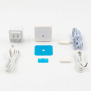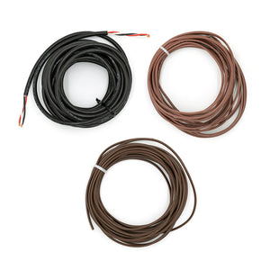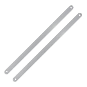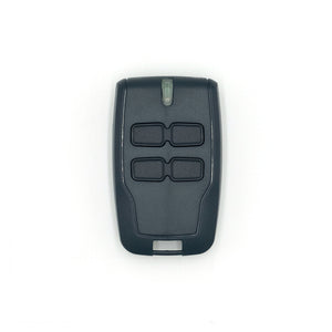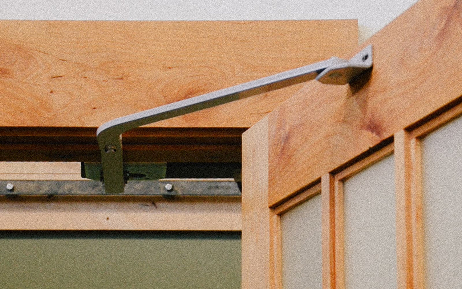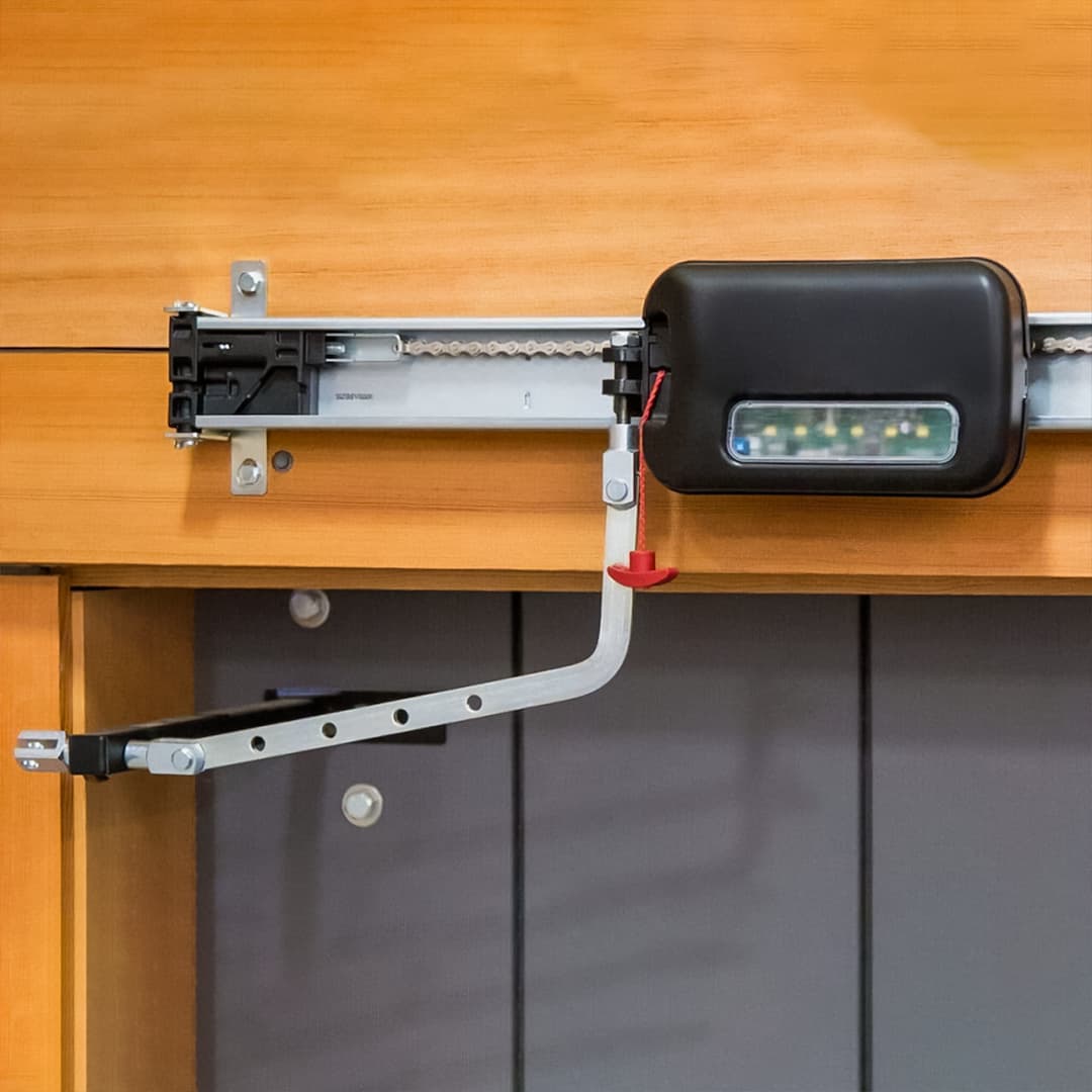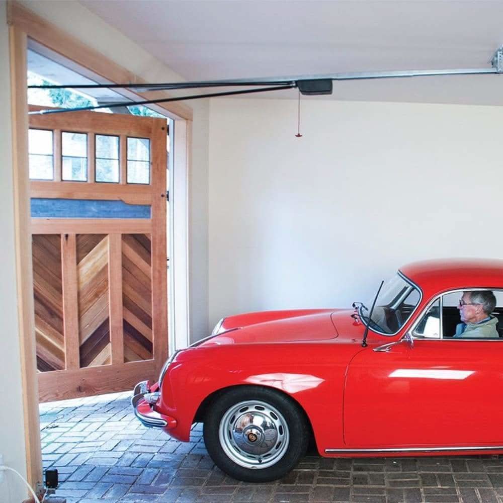


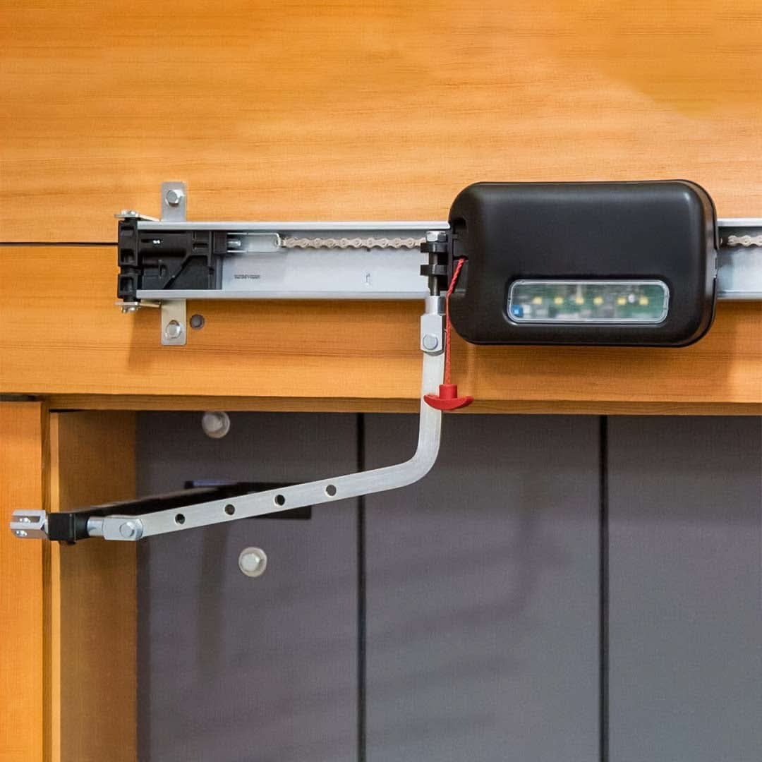


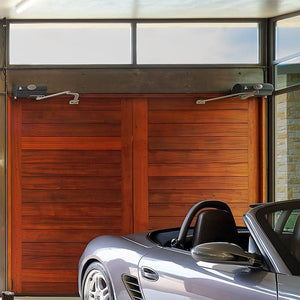
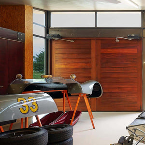
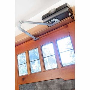
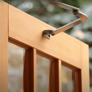
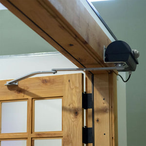
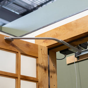
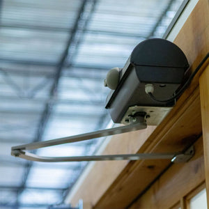
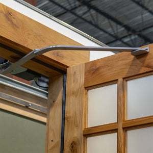

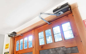
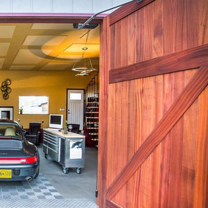
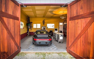
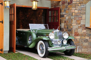
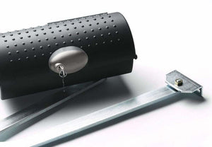
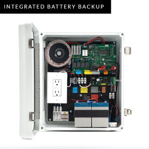

The Franklin Autoswing automatic door kit is designed to swing open garage/carriage doors with the click of a button. With European engineering, the design of this carriage garage door hardware is compact, smooth, and quiet. The motors mount above the opening, without a track along with the ceiling, leaving the space open from floor to ceiling. Customize this garage carriage door hardware kit with accessories - Homelink Compatibility, Interior or Exterior Wireless wall button, Battery Backup, and even a Solar module!
Note: garage doors are not included, this product listing is for the opener kit only.
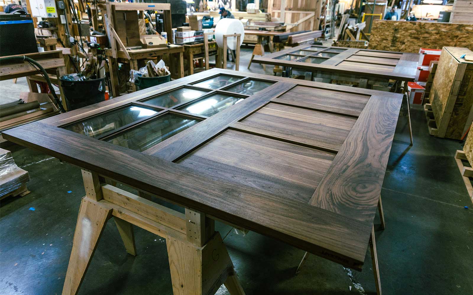
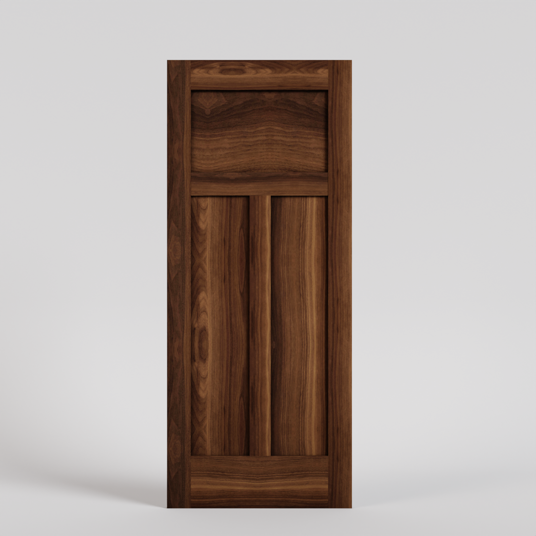
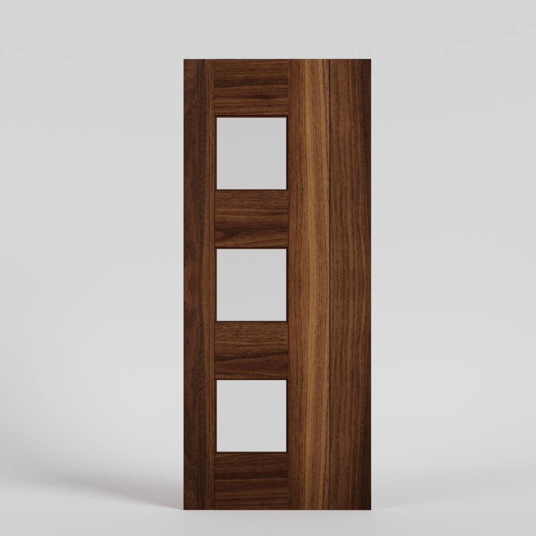
Check out our collection of carriage doors to pair with your Franklin!